
Engineered magnetic material production
Non-contact drive

Magnetic couplings.
Hermetic, no seal.

Non-contact magnetic couplings for hermetic, leak-free torque transmission. No dynamic seal, no leakage path, no contamination risk. Disc, barrel and synchronous geometries. Specified for chemical, pharmaceutical, food, semiconductor and medical applications.

Coupling types

Disc, barrel, synchronous.

  • Disc (Axial)

    Two magnet discs on parallel shafts with a separating can. Axial torque transfer, common in pumps and mixers.

  • Barrel (Concentric)

    Cylindrical magnets on inner and outer parts. Higher torque capacity, hermetic seal.

  • Synchronous

    Synchronous torque transmission with no slip. Used in precise positioning applications.

Product geometry

Couplings we build.

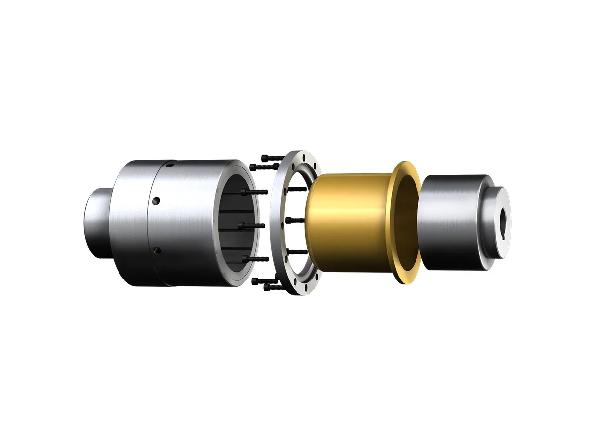
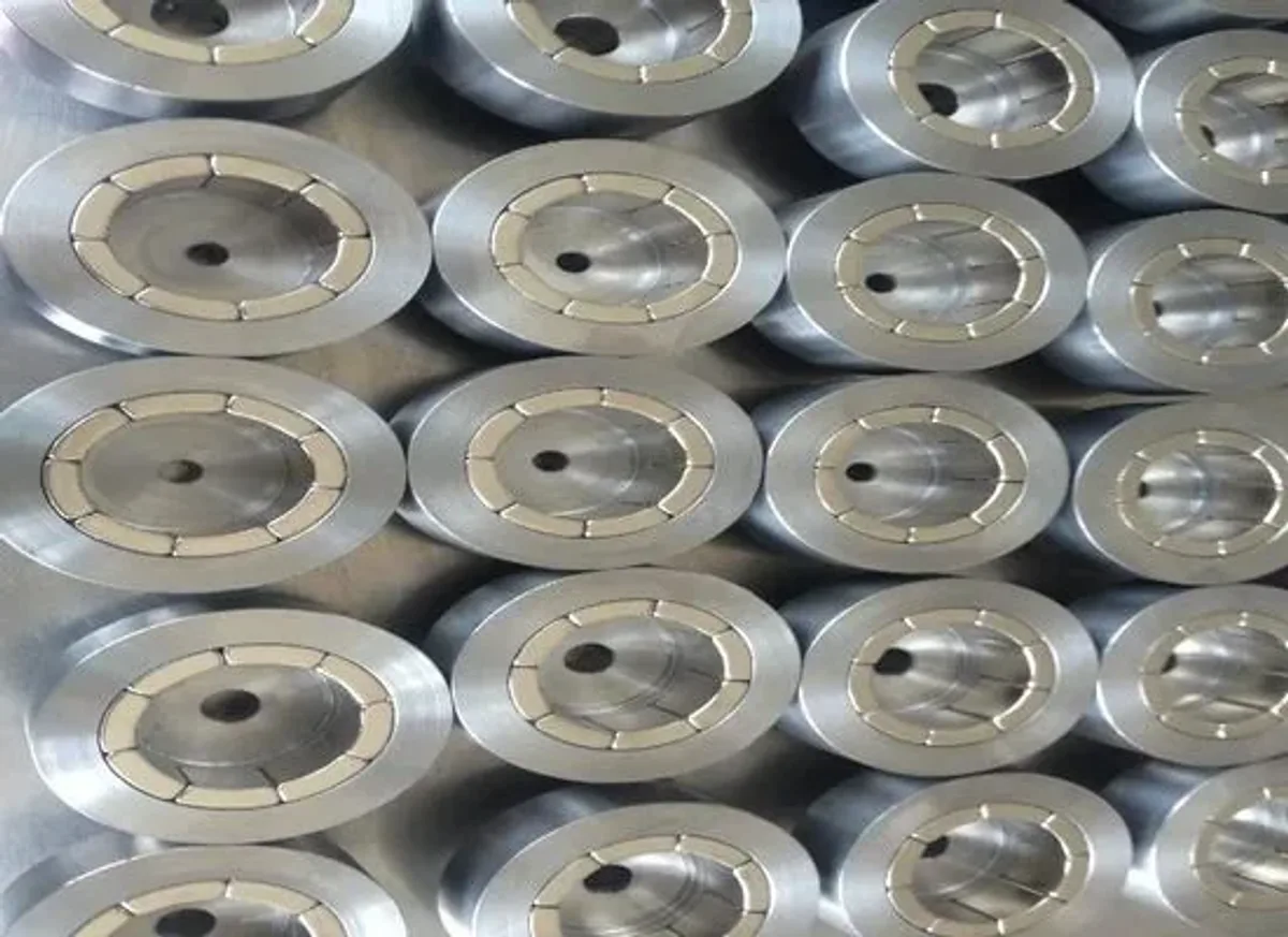
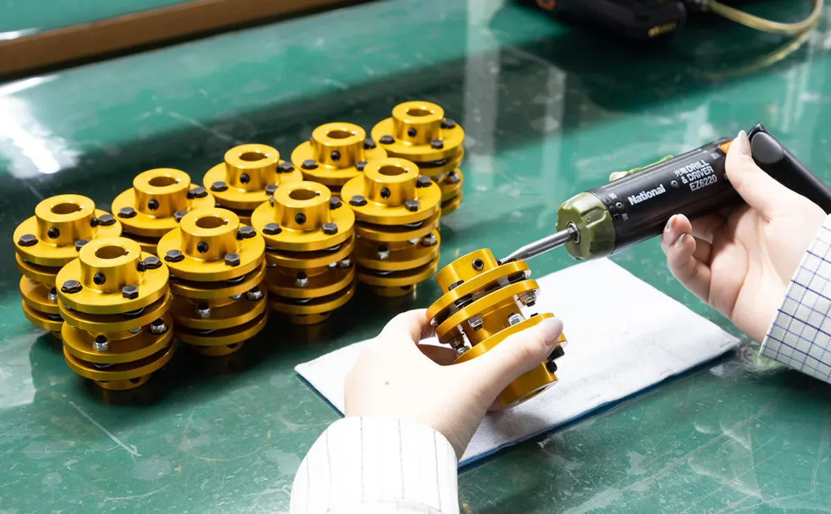
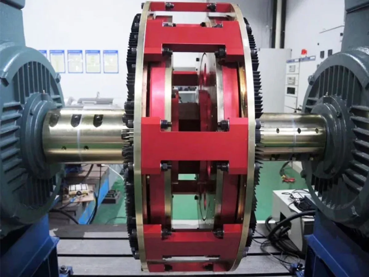
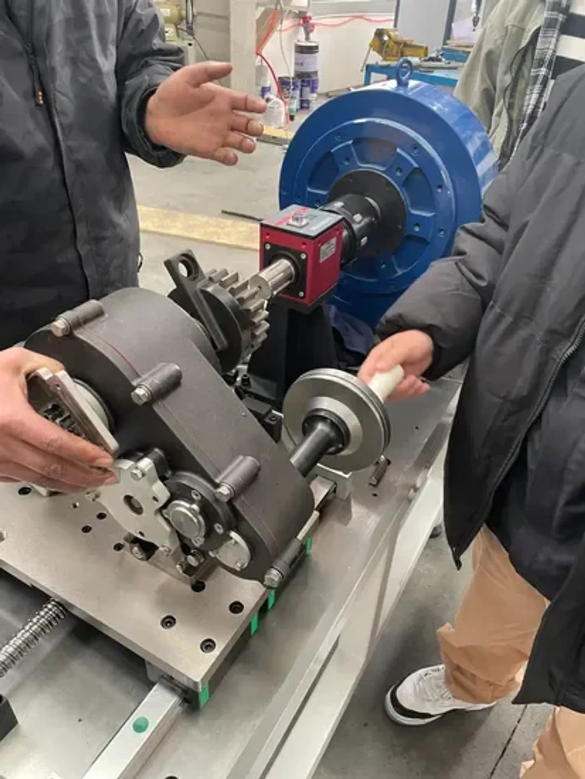
Representative magnetic couplings showing magnet layout, containment shell and hub interface.

  • Magnetic coupling shown as separated components
    01

    Exploded view

    Magnet, hub and containment shell separated

  • Stainless steel magnetic coupling assembly
    02

    Stainless steel

    Stainless containment for corrosive duty

  • Magnetic coupling showing its internal magnet layout
    03

    Internal magnet layout

    Magnet arrangement visible inside the coupling

Capabilities

What we hold.

  • Torque range 0.5–5,000 Nm
  • Air gap 2–15mm typical
  • Speed Up to 10,000 rpm
  • Materials NdFeB, SmCo, encapsulation
  • Can material SS 316L, Hastelloy, titanium
  • Validation Torque-speed curve, leak test
Applications

Where magnetic couplings are specified.

  • Chemical and pharmaceutical pumps

  • Food and beverage processing

  • Semiconductor wet process

  • Medical and diagnostic equipment

  • Subsea and offshore systems

  • Bioreactors and sterile mixing

Specification guide

Choose a magnetic coupling with the application in view.

A magnetic coupling is selected around torque, speed, air gap, temperature, containment and upset conditions. The magnet set is only one part of the hermetic torque path.

A good fit when

The material earns its place.

  • Pumps, mixers and drives that need a sealed process boundary
  • Applications where eliminating a dynamic shaft seal reduces leakage or contamination risk
  • Systems with a defined torque-speed envelope and controlled air gap
  • Chemical, pharmaceutical, food, semiconductor or medical equipment requiring clean interfaces

Check before release

Resolve these trade-offs early.

  • Rated torque must include startup, stall, viscosity, acceleration and transient loads
  • The containment can introduces an air-gap and eddy-current trade-off at speed
  • Over-temperature, overload or loss of synchronization can damage magnets or the can
  • Hygiene, cleanability, pressure rating and material compatibility belong in the same review
RFQ preparation

Give engineering the information that changes the answer.

A drawing alone may not define the magnetic requirement. These inputs help us recommend the right grade, geometry, coating and inspection plan instead of quoting a generic part.

01

Torque and speed

Provide continuous, peak, startup and stall torque, speed range, acceleration, duty cycle and the driven fluid or load.

02

Process boundary

Define pressure, vacuum, leakage criterion, fluid chemistry, temperature, cleanability and the containment material requirement.

03

Envelope and interfaces

Share shaft, flange, bearing, can, air-gap and mounting dimensions, plus allowable misalignment and runout.

04

Failure modes

Describe dry run, blocked shaft, thermal runaway, loss of synchronization, reverse rotation and maintenance conditions.

Acceptance planning

Define the evidence before the first production order.

Inspection scope should follow the failure mode. We can align the report format, sample quantity and release criteria during drawing review.

01

Torque-speed curve

Test the coupling across the agreed speed and torque range, including startup, transient and thermal conditions.

02

Containment integrity

Use the specified leak, pressure, cleanliness or sterilization method on the final process boundary.

03

Temperature rise

Measure magnet, can, bearing and process-side temperatures under representative load and speed.

04

Runout and alignment

Verify concentricity, axial position, air gap and shaft alignment because mechanical error reduces torque margin.

Buyer questions

The short version before you send a drawing.

What is the main benefit of a magnetic coupling?

It transfers torque across a sealed boundary without a dynamic shaft penetration, which can reduce leakage paths and contamination risk when the complete system is designed and validated correctly.

How do I size a coupling?

Start with continuous and peak torque, speed, duty cycle, temperature, air gap, process pressure and fluid properties. Startup, stall and transient conditions are essential for selecting margin.

Can the containment can be non-metallic?

Material selection depends on pressure, stiffness, chemical compatibility, temperature, permeability, eddy-current loss and manufacturing method. The can should be reviewed as a system component, not chosen separately.

Global magnet shipment preparation
Start a project

Send the drawing. Tell us
what the magnet has to do.

Our engineering team can review material, operating conditions, magnetic requirements, manufacturing route and validation needs before quotation.

RFQ channel rfq@china-empire.com
General service services@china-empire.com
Engineering review Drawings and requirements welcome