Remanence
Residual magnetic flux density at zero applied field after saturation.
T · mT · G · kGFROM MATERIAL TO COMPONENT
Magnetic quantities, clear calculations and the interfaces that shape a component.
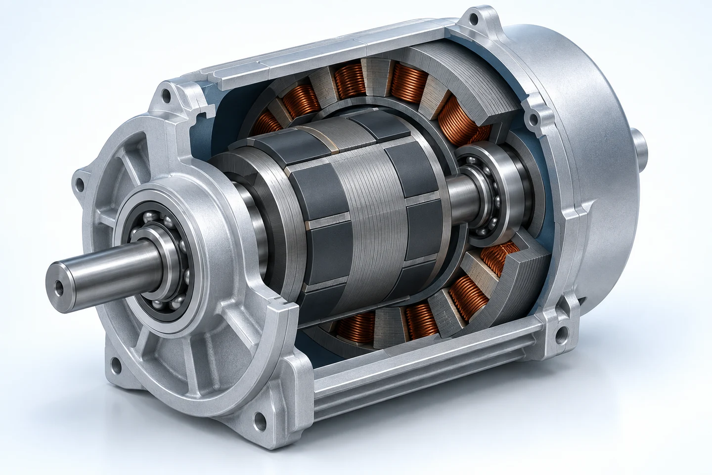
READ THE MATERIAL DATA
Compare the same quantity, units and test conditions.
Residual magnetic flux density at zero applied field after saturation.
T · mT · G · kGReverse field strength at which magnetic flux density B reaches zero.
A/m · kA/m · OeReverse field strength at which magnetic polarization J reaches zero.
A/m · kA/m · OeMaximum magnitude of B × H on the second-quadrant normal demagnetization curve.
kJ/m³ · MGOeRemanence is a material property. The field at a working point also depends on magnet geometry, the magnetic circuit and the gap.
PRACTICAL REFERENCE TOOLS
Conversions and worked examples for preliminary engineering discussions.
UNITS
1 T = 10 kG
A unit conversion does not determine a product's performance or material grade.
WORKED EXAMPLE
Assumed inputs below illustrate a linear calculation. They are not an Empire grade specification.
Bᵣ(T) = Bᵣ(T₀) × [1 + αBᵣ × (T − T₀) / 100]
Use a coefficient established for the selected grade and temperature interval. This approximation does not predict irreversible demagnetization, coercivity or a safe operating temperature.
Total indicator variation is the difference between the largest and smallest indicator readings for the specified setup.
An arithmetic example, not a rotor tolerance or inspection result. Specify the datum, measured surface, indicator direction and rotation setup on the drawing.
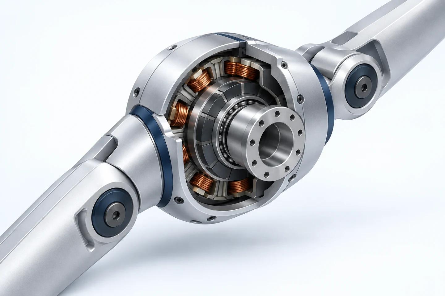
ENGINEER THE INTERFACES
Define the mechanical, magnetic and environmental boundary together.
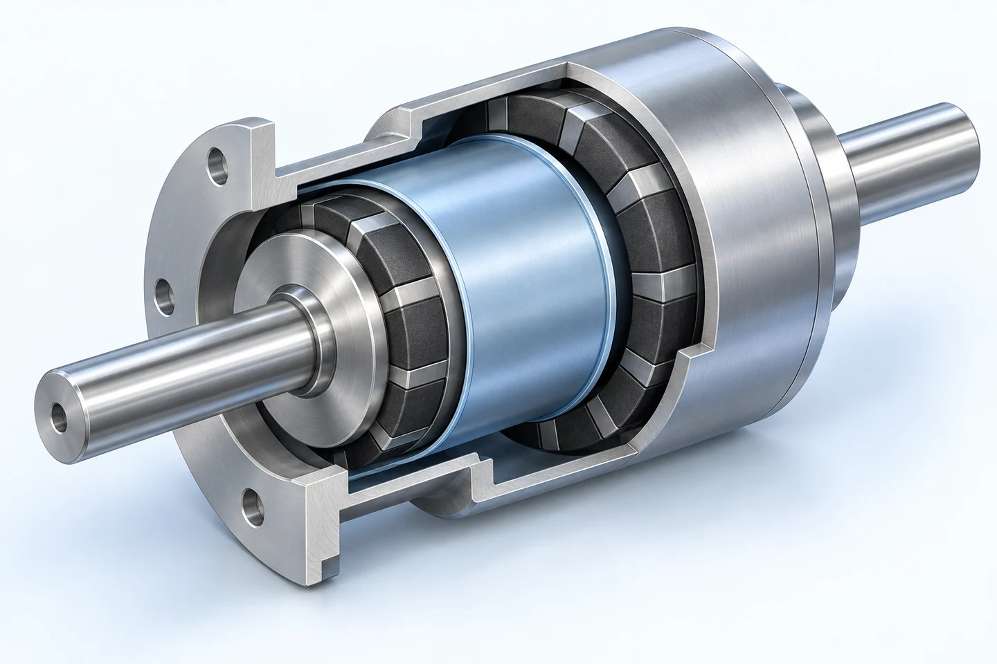
FROM REFERENCE TO RELEASE
Reference data supports material selection. The supplied part is defined by its agreed drawing, material requirements and inspection plan.
Discuss Your ComponentTECHNICAL BASIS
General definitions and methods below support this reference. Third-party publications do not certify Empire products.
Reference edition 2026.09 · Published 27 September 2026