Insert & polymer
Identify the magnetic insert, polymer and critical interfaces.
Magnetic inserts integrated with polymer bodies. Review the insert, molding conditions and finished interfaces as one component.
An overmolded component brings magnetic material, polymer and mechanical interfaces into one design. We review the molding process, exposure conditions, retention and critical dimensions together, with validation matched to the finished component.
START WITH YOUR REQUIREMENTS
Identify the magnetic insert, polymer and critical interfaces.
Share molding conditions and the operating environment.
Agree retention, encapsulation and dimensional acceptance.
FORMS & CONFIGURATIONS
Representative product forms. Final geometry, dimensions and material are confirmed against your drawing.
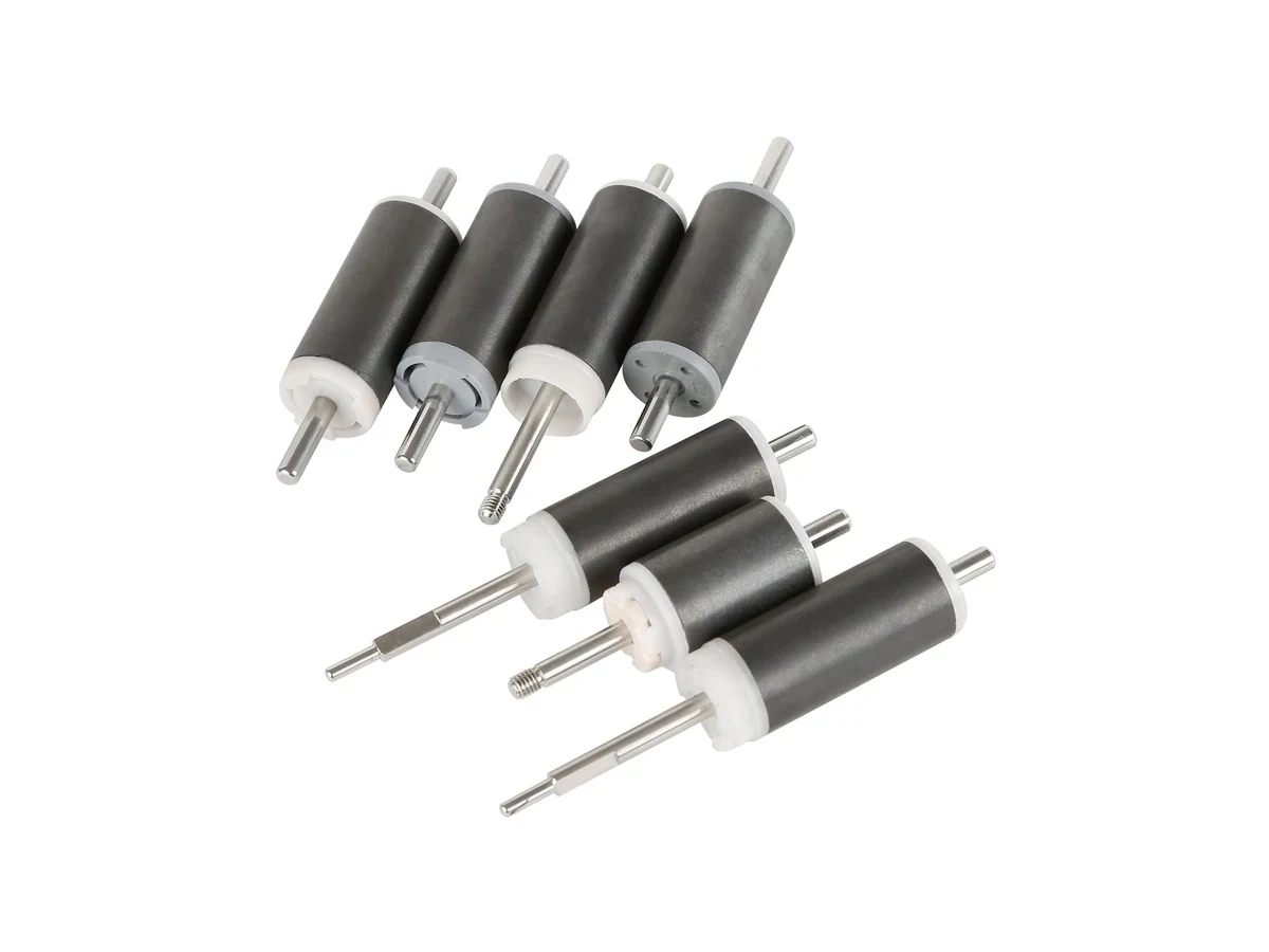
Cylindrical magnetic components integrated with shafts.
Review This Form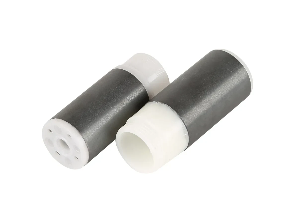
Ferrite magnet sealed inside a polymer body
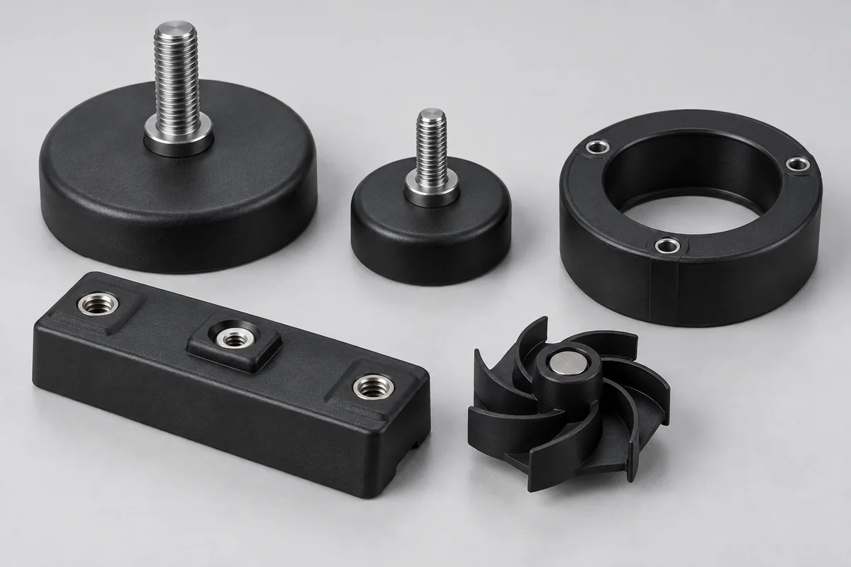
Review This FormBlack encapsulated magnetic mounts and molded components.
View Configuration GuideDESIGN & SELECTION
Grade, orientation and coating
Material compatibility and molding route
Datum, fit and exposed interfaces
Select a category to see the inputs to confirm.
Review This ConfigurationSelection identifies the review scope. Materials, ratings and acceptance criteria remain subject to engineering confirmation.
ENGINEERING REVIEW
Review polymer exposure, insert temperature and locating features together with the molding sequence.
Specify temperature, chemicals, humidity, pressure, UV, sterilization, flame rating and expected service life for the polymer shell.
Provide magnet grade, coating, magnetization state, insert datum, keep-out zones, adhesive and the allowable magnetic shift.
Show clips, seals, ribs, bosses, draft, parting line, gate preference, ejection constraints and critical assembly dimensions.
State annual volume, cycle target, cavity strategy, traceability, cosmetic limits and any automotive or medical documentation needs.
QUALITY & RELEASE
Verification follows the component’s function and the agreed inspection plan.
Measure magnet location, orientation, stand-off and critical molded dimensions against the functional drawing.
Test flux, pull, switching or sensor response on the final molded component, not only on the loose magnet.
Run the agreed temperature, humidity, chemical, pressure or sterilization exposure and retest function afterward.
Inspect voids, cracks, flash, weld lines, pull-off or torque retention and any leak or sealing requirement.
PRODUCT QUESTIONS
Insert molding and other encapsulation routes can be evaluated when the magnet, polymer and process window are compatible. The insert must be protected from heat, pressure and movement during molding.
The polymer itself may not change the magnet's intrinsic grade, but position, orientation, air gap, temperature and nearby material can materially change the functional field or sensor response.
Tooling responsibility and ownership can be defined during DFM review. The design should freeze the magnetic datum and critical molded interfaces before tool release.
CONTINUE EXPLORING
APPLICATION REVIEW
Share the insert drawing, polymer requirements and critical molded faces.
Discuss This Specification