Torque & speed
Share running, start-up and overload conditions.
Non-contact torque transmission for separated mechanical systems. Review torque, working gap and containment conditions together.
Coupling performance depends on more than magnet strength. We review required torque, speed, working gap, containment materials and temperature together, helping define an assembly and verification method suited to the operating environment.

START WITH YOUR REQUIREMENTS
Share running, start-up and overload conditions.
Define the working gap and containment material.
Identify temperature, exposure and the verification method.
FORMS & CONFIGURATIONS
Representative product forms. Final geometry, dimensions and material are confirmed against your drawing.
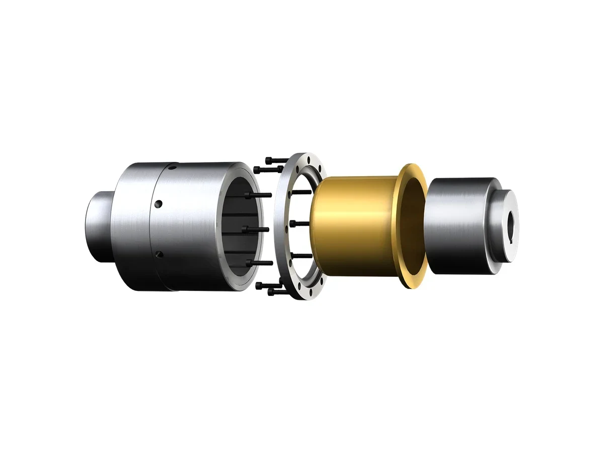
Magnet, hub and containment shell separated
View Configuration Guide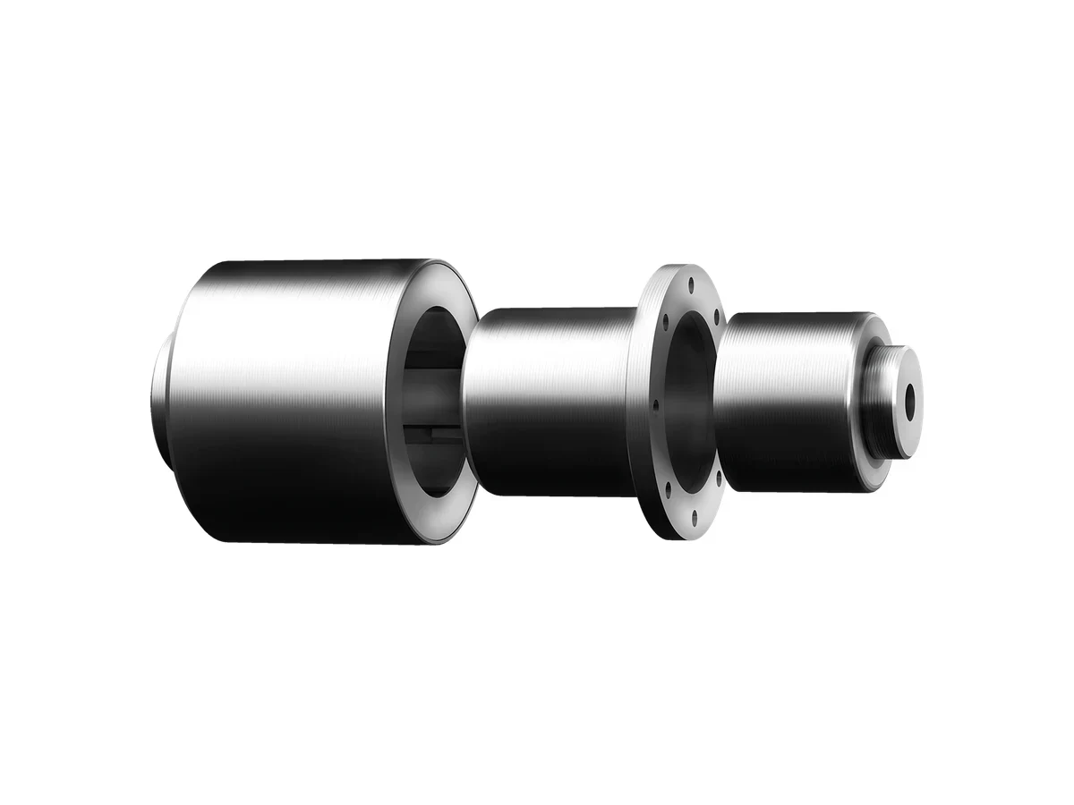
Stainless containment for corrosive duty
Review This FormMagnet arrangement visible inside the coupling
View Configuration Guide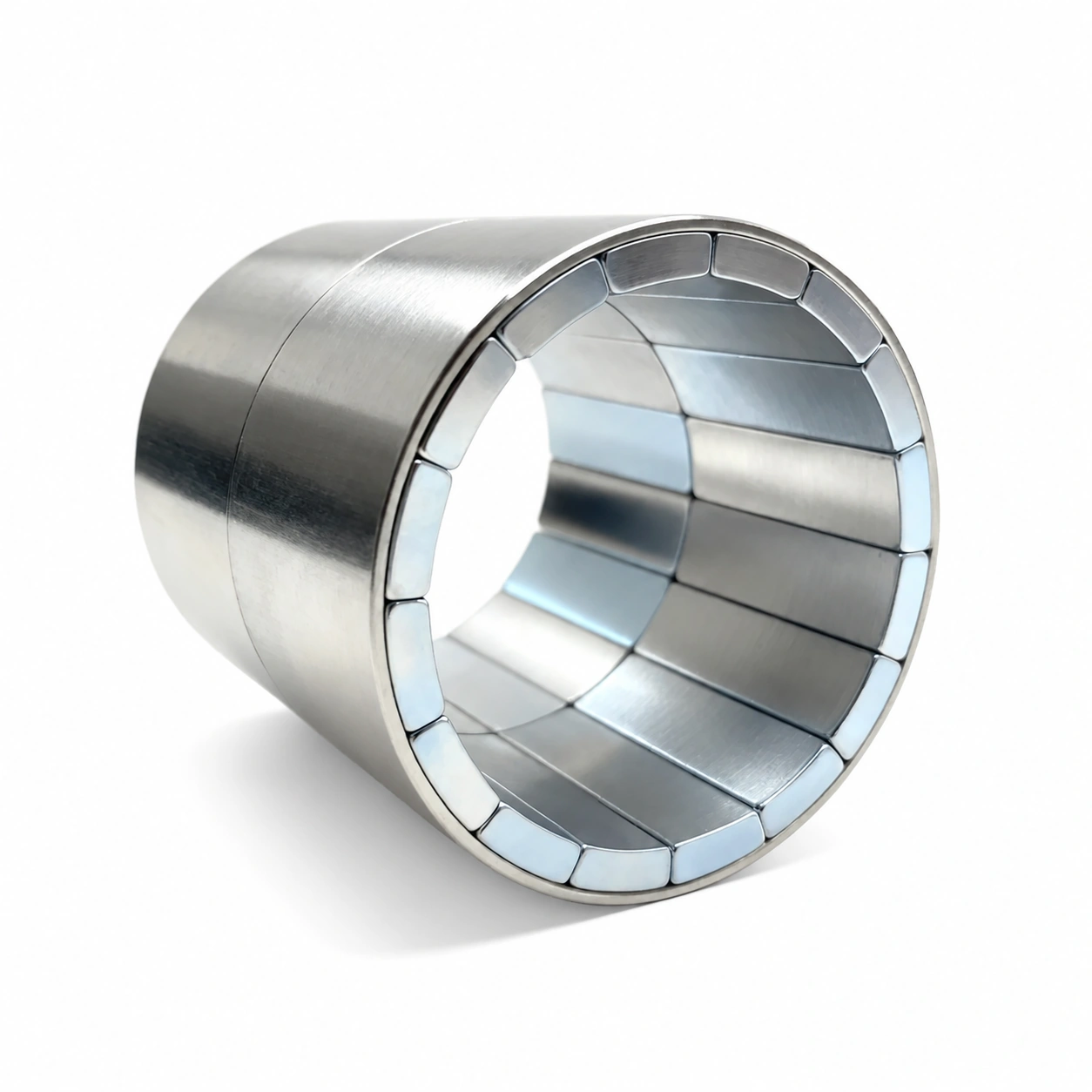
Magnet segments retained inside a cylindrical carrier.
View Configuration GuideDESIGN & SELECTION
Drive interface and envelope
Driven interface and alignment
Material and pressure boundary
Clearance, temperature and torque
Select a category to see the inputs to confirm.
Review This ConfigurationSelection identifies the review scope. Materials, ratings and acceptance criteria remain subject to engineering confirmation.
ENGINEERING REVIEW
Resolve the containment boundary, effective gap and full torque duty before selecting the coupling layout.
Provide continuous, peak, startup and stall torque, speed range, acceleration, duty cycle and the driven fluid or load.
Define pressure, vacuum, leakage criterion, fluid chemistry, temperature, cleanability and the containment material requirement.
Share shaft, flange, bearing, can, air-gap and mounting dimensions, plus allowable misalignment and runout.
Describe dry run, blocked shaft, thermal runaway, loss of synchronization, reverse rotation and maintenance conditions.
QUALITY & RELEASE
Verification follows the component’s function and the agreed inspection plan.
Test the coupling across the agreed speed and torque range, including startup, transient and thermal conditions.
Use the specified leak, pressure, cleanliness or sterilization method on the final process boundary.
Measure magnet, can, bearing and process-side temperatures under representative load and speed.
Verify concentricity, axial position, air gap and shaft alignment because mechanical error reduces torque margin.
PRODUCT QUESTIONS
It transfers torque across a sealed boundary without a dynamic shaft penetration, which can reduce leakage paths and contamination risk when the complete system is designed and validated correctly.
Start with continuous and peak torque, speed, duty cycle, temperature, air gap, process pressure and fluid properties. Startup, stall and transient conditions are essential for selecting margin.
Material selection depends on pressure, stiffness, chemical compatibility, temperature, permeability, eddy-current loss and manufacturing method. The can should be reviewed as a system component, not chosen separately.
CONTINUE EXPLORING
APPLICATION REVIEW
Send the isolation sleeve, working gap and torque-speed duty.
Discuss This Specification