Shaft & layout
Share the shaft interfaces, magnet layout and mating parts.
Magnets, shafts and retention for motor and drive applications. Review magnetic performance and mechanical interfaces as one assembly.
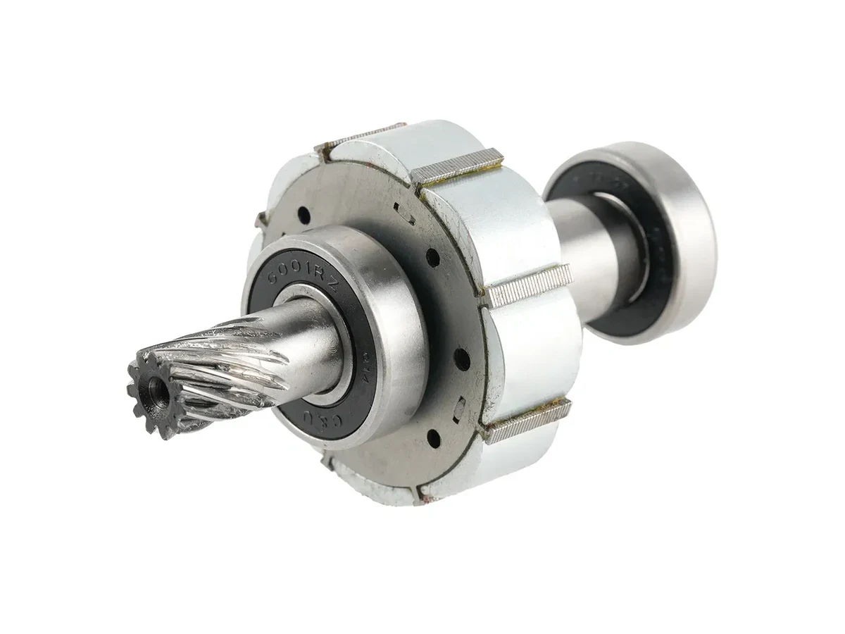
A rotor must meet magnetic and mechanical requirements at the same time. We review the magnet layout, shaft interfaces, retention, operating speed and temperature together, with balance and inspection requirements defined before production release.
START WITH YOUR REQUIREMENTS
Share the shaft interfaces, magnet layout and mating parts.
Define rotational speed, temperature and applied loads.
Agree retention, runout, balance and inspection requirements.
FORMS & CONFIGURATIONS
Representative product forms. Final geometry, dimensions and material are confirmed against your drawing.
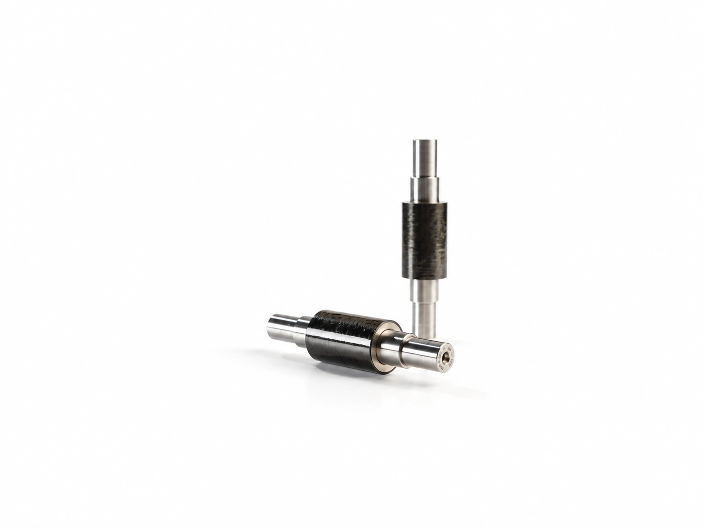
Carbon-fibre sleeved for high rotational speed
Review This FormSegmented magnets assembled onto a shaft
Review This Form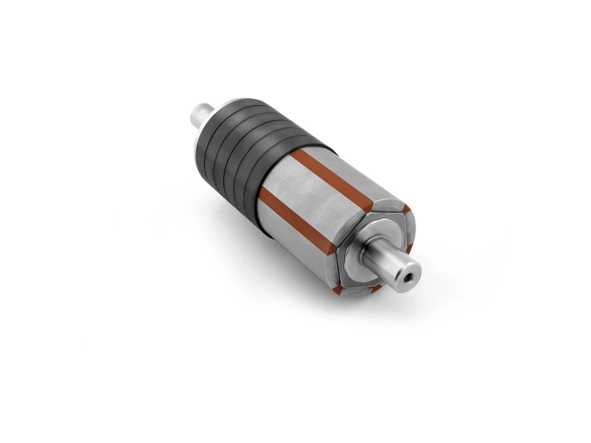
Bonded magnet ring carried on a steel hub
Review This Form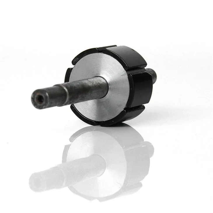
Segmented permanent-magnet rotor on a shaft.
View Configuration GuideWHAT WE SUPPLY
Permanent magnets integrated with a shaft, core or carrier to the approved configuration.
Drawing-defined fits, retention features and mating components.
The bill of materials and inspection plan define the supplied assembly and its release records.
DESIGN & SELECTION
Datums, fit and runout
Material, polarity and position
Material and retention method
Axial stop and assembly reference
Select a category to see the inputs to confirm.
Review This ConfigurationSelection identifies the review scope. Materials, ratings and acceptance criteria remain subject to engineering confirmation.
ENGINEERING REVIEW
Define speed and load cases, shaft datums and magnet retention before agreeing balance or runout limits.
Share speed, torque, power, duty cycle, temperature at the rotor and the electrical operating point. Include overspeed and fault cases.
Provide shaft datum, bearing arrangement, rotor OD, stack length, runout, fit, key or spline details and assembly sequence.
Provide pole count, magnetizing direction, air gap, flux or back-EMF target, harmonic limits and grade preference if known.
State sleeve, band, adhesive, pocket, bridge or overmold concept, plus burst-speed, shock, balance and service-life requirements.
QUALITY & RELEASE
Verification follows the component’s function and the agreed inspection plan.
Define balance grade, correction plane, speed, fixture and residual unbalance limits. Report the condition of the final assembly.
Validate the agreed overspeed and thermal condition, with inspection for movement, cracks, adhesive failure or sleeve damage.
Map air-gap flux and, where applicable, verify back-EMF waveform, pole position and harmonic content against the motor target.
Measure critical diameters, shaft runout, magnet-to-shaft concentricity and bearing datum relationships on the released assembly.
PRODUCT QUESTIONS
The assembly scope can include magnets, shaft, hub, sleeve or band, adhesive, balancing and agreed validation. The exact make-or-buy boundary should be defined from the drawing and motor interface.
The most useful starting package combines motor duty, rotor geometry, air gap, speed and temperature with the magnetic target and retention concept.
Balance, dimensional, flux and waveform reports can be aligned to the program's acceptance plan. The required fixture, sample quantity and limits should be agreed before production.
CONTINUE EXPLORING
APPLICATION REVIEW
Send the shaft drawing, operating speed and retention requirements.
Discuss This Specification