Target field
Define the field strength and uniformity required in use.
Oriented magnet arrays for a defined field region. Connect the target field, working volume and segment retention in one review.
The arrangement of each segment determines how the array performs. We start with the required field, working volume and assembly envelope, then review segmentation, orientation, retention and the measurement plan as one system.
START WITH YOUR REQUIREMENTS
Define the field strength and uniformity required in use.
Show the useful field region, clearances and assembly envelope.
Agree segment orientation, retention and the field-map fixture.
FORMS & CONFIGURATIONS
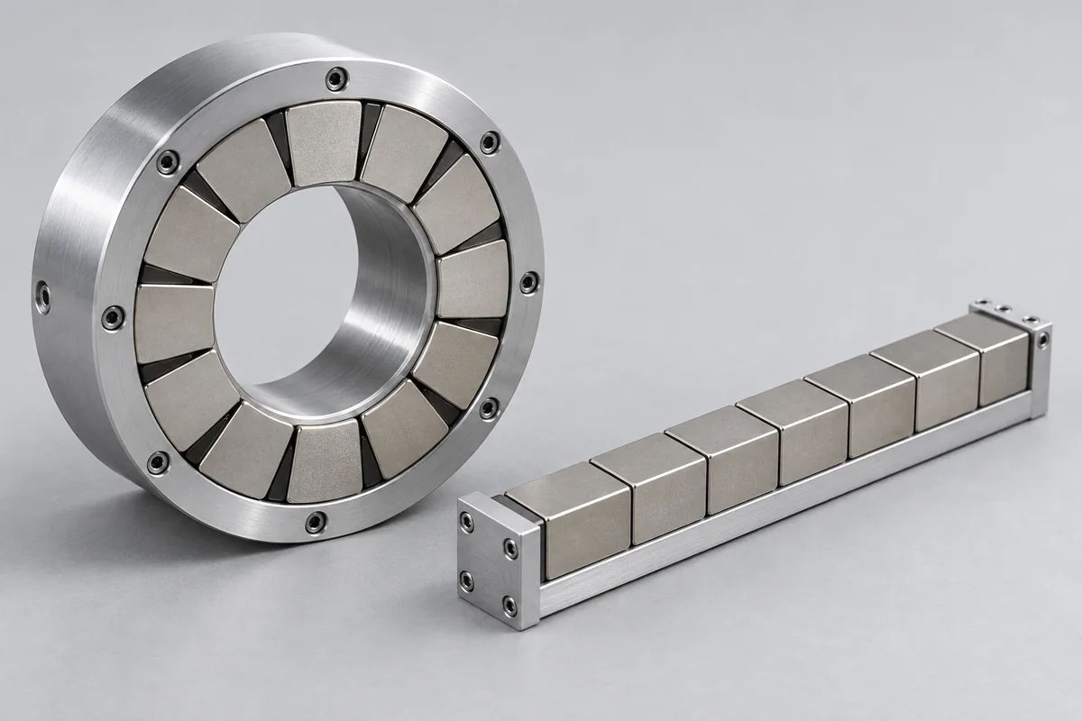
Representative product forms. Final geometry, dimensions and material are confirmed against your drawing.
Segmented cylindrical and linear permanent-magnet arrays.
View Configuration GuideDESIGN & SELECTION
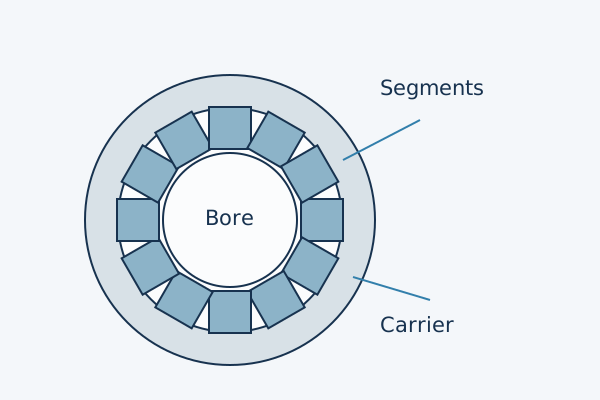
Segment geometry, carrier and working volume are defined for each project. Magnetization directions and tolerances follow the approved drawing.
Direction patterns. Confirm the magnetization schedule, target field region and measured field map for the actual geometry.
Select a category to see the inputs to confirm.
Review This ConfigurationSelection identifies the review scope. Materials, ratings and acceptance criteria remain subject to engineering confirmation.
ENGINEERING REVIEW
Specify the measurement volume and field target, then resolve segment orientation and structural retention.
Provide the field target, measurement plane, useful volume, air gap, field direction and allowable uniformity variation.
Share length, diameter, segment count, pole count, magnetization angle, keying features and non-magnetic structural parts.
Define temperature, vibration, centrifugal or transport loads, adhesive or mechanical retention and service-life requirements.
Plan magnetized or unmagnetized assembly, handling fixtures, keep-away zones, polarity marking and packaging constraints.
QUALITY & RELEASE
Verification follows the component’s function and the agreed inspection plan.
Map the field across the specified working volume using a calibrated Hall system and the released fixture or coordinate system.
Verify segment polarity, magnetization angle, sequence and indexing before final bonding or encapsulation.
Report field uniformity in the working zone and stray-field readings at agreed external locations.
Test the final array under temperature, vibration or centrifugal conditions that represent the application.
PRODUCT QUESTIONS
Not always. A Halbach arrangement can concentrate field and reduce reliance on back-iron, but structural stiffness, thermal paths, leakage, saturation and assembly constraints still determine the final design.
Unmagnetized segment supply may simplify assembly and safety, while some programs require pre-magnetized matched parts. The sequence depends on the fixture and array architecture.
Define the working volume, coordinate system, measurement spacing, temperature and allowable deviation. 'Uniform' without a measurement envelope is not an acceptance criterion.
CONTINUE EXPLORING
APPLICATION REVIEW
Share the working volume, field direction and allowed variation.
Discuss This Specification